

RC Transmitter – New PCB
After working with earlier versions of the RC transmitter hardware, I ran into a few small issues that made me rethink the PCB design.
In this update, I’ll walk through the changes I made to both the transmitter and receiver PCBs to improve signal stability and add a few useful features.
You’ll see how I tackled noise problems with additional capacitors, added extra I/O options, and reworked joystick channels for redundancy.

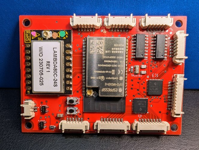
RX PCB:
The RX PCB had a small problem due to the voltage divider being connected to the voltage regulator instead of the battery.
Other small updates:
- Extra Input/Output connector
- Coupling and Decoupling Capacitors
- Possibility to add a resistor for the piezo buzzer, if needed
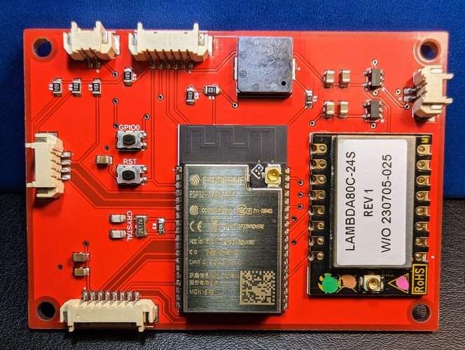
TX PCB:
Because of the noise, I had to add coupling and decoupling capacitors for each IC as well as for the voltage regulators.
A bigger change is the fact that for the joysticks, there’s a redundancy channel allocated for each axis. This was possible because the IC had 8 channels, while for the joystick,s it was needed only 4.
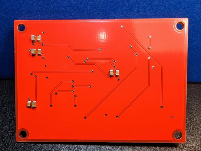
On the back of the PCB, there’s also a new connector that could be used to INPUT or to OUTPUT data.