

RC Transmitter Wiring Tutorial – ESP32 / SX1280
There's something oddly satisfying about connecting wires and watching a project come to life.
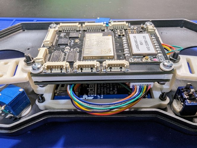
Now, we'll tackle the wiring for the custom RC transmitter using the ESP32 and SX1280.

I decided to keep this separate from the build in order to make all the steps easier to follow.
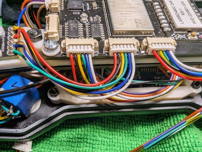
Note: Because the first pin is GND and my connector starts with a RED wire, it will be a bit confusing.
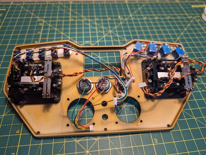
Also, I used pictures from a different build, where I tested a different shell, but that doesn’t really matter because, in the build tutorial, I’m using the final shell.
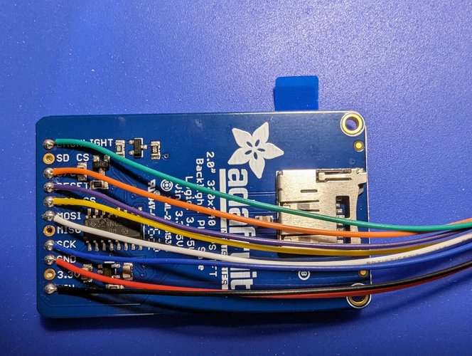
| TFT Display | PCB |
|---|---|
| Backlight | GPIO27 |
| D/C | GPIO4 |
| Reset | GPIO15 |
| LCD CS | GPIO25 |
| MOSI | GPIO13 |
| SCK | GPIO14 |
| GND | GND |
| VIN | 3.3v |
| Push Buttons | PCB |
|---|---|
| Button 1 (green wire ) | GPIO34 |
| Button 2 (yellow wire) | GPIO39 |
| Button 3 (black wire) | GPIO36 |
| Common GND (red wire) | GND |
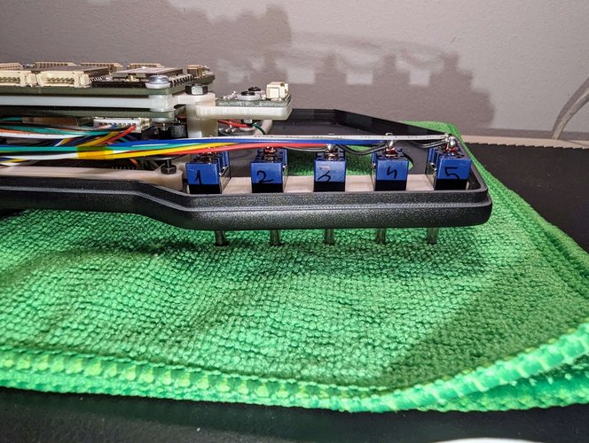
| Switches | PCB |
|---|---|
| Switch #1 – Black Wire | SW1 |
| Switch #2 – Yellow Wire | SW2 |
| Switch #3 – Green Wire | SW3 |
| Switch #4 – Blue wire | SW4 |
| Switch #5 – White wire | SW5 |
| Common GND (red wire) | GND |
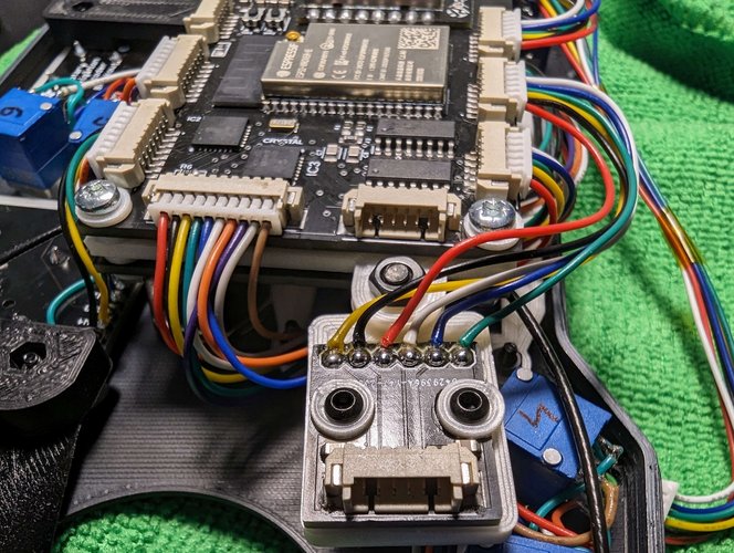
For the potentiometers, please check the datasheet and make sure to connect the right VCC to 3.3V and GND to GND. In case you invert them, the reading will also be inverted.
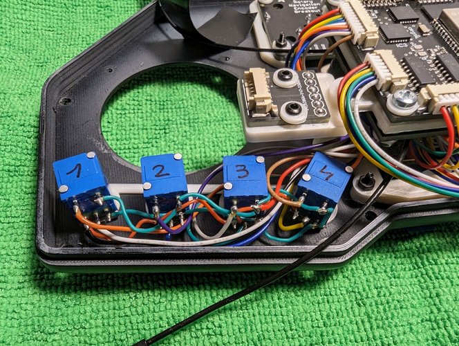
| Potentiometer | PCB |
|---|---|
| POT #1 signal | POT1 |
| POT #2 signal | POT2 |
| POT #3 signal | POT3 |
| POT #4 signal | POT4 |
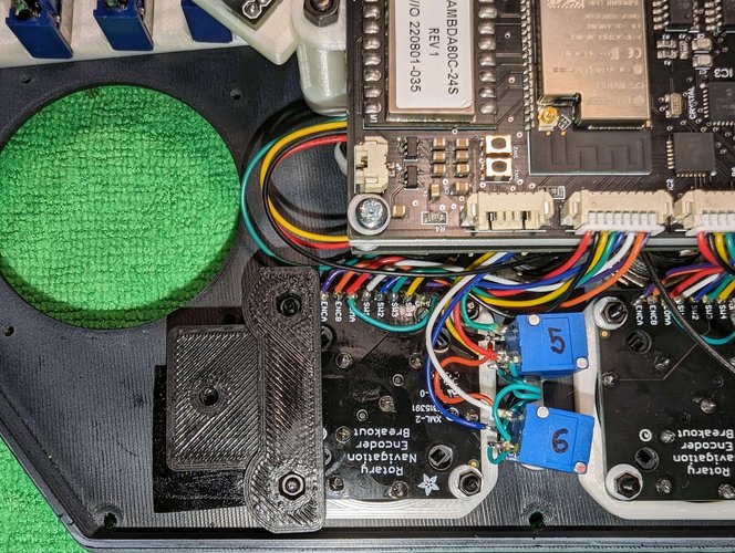
| POT #5 signal | POT5 |
| POT #6 signal | POT6 |
| Pot Switch #1 | POT1_SW |
| Pot Switch #2 | POT2_SW |
| Pot Switch #3 | POT3_SW |
| Pot Switch #4 | POT4_SW |
| Pot Switch #5 | POT5_SW |
| Pot Switch #6 | POT6_SW |
| Common GND | GND |
| Common VCC | 3.3V |
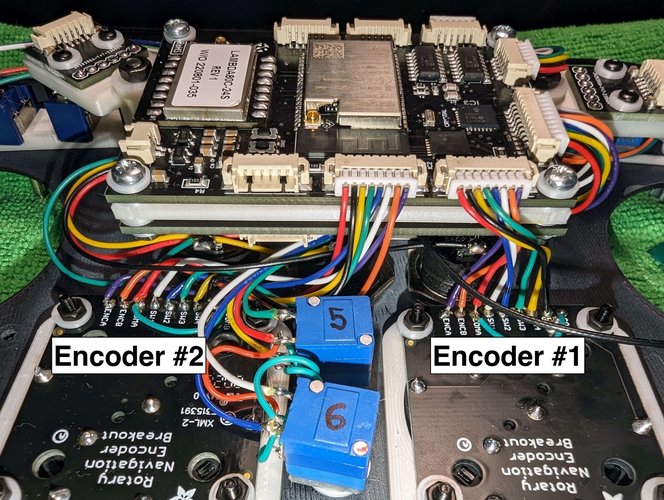
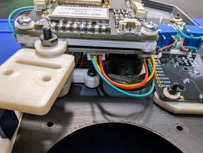
| Encoder #2 | PCB |
|---|---|
| COMB | GND |
| SW5 | ANO2_SW5 |
| SW4 | ANO2_SW4 |
| SW3 | ANO2_SW3 |
| SW2 | ANO2_SW2 |
| SW1 | ANO2_SW1 |
| COMA | GND |
| ENCB | ANO2_ENCB |
| ENCA | ANO2_ENCA |
| Encoder #1 | PCB |
|---|---|
| COMB | GND |
| SW5 | ANO1_SW5 |
| SW4 | ANO1_SW4 |
| SW3 | ANO1_SW3 |
| SW2 | ANO1_SW2 |
| SW1 | ANO1_SW1 |
| COMA | GND |
| ENCB | ANO1_ENCB |
| ENCA | ANO1_ENCA |
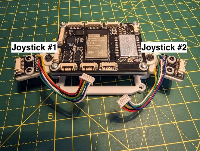
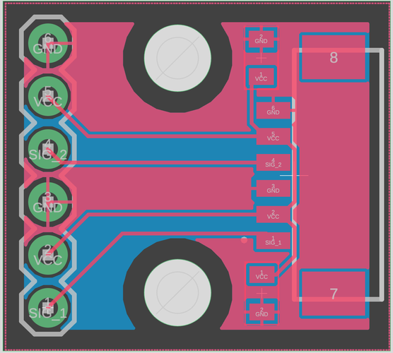
| Joystick #1 PCB | PCB |
|---|---|
| GND (second GND) | GND |
| VCC (second VCC) | 3.3V |
| SIG_1 | JOYSTICK_X1 |
| GND (first GND) | GND |
| VCC (first VCC) | 3.3V |
| SIG_2 | JOYSTICK_Y1 |
| Joystick #2 PCB | PCB |
|---|---|
| GND (second GND) | GND |
| VCC (second VCC) | 3.3V |
| SIG_1 | JOYSTICK_X1 |
| GND (first GND) | GND |
| VCC (first VCC) | 3.3V |
| SIG_2 | JOYSTICK_Y1 |
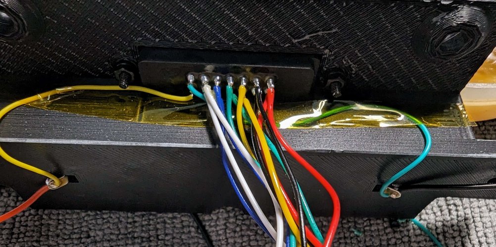
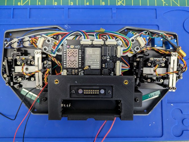
For the programming connector, the far left 2 pins are connected directly to the battery.
It could be used to either charge the battery or, just power the remote from an external source.
The yellow one is VCC, while the Blue(ish) one is GND.
I’ll only list the FTDI pinout for a single PCB, as I’m using the same pinout for the second one.
You can see that I have 2x white, blue, green, yellow, black and red wires.
| Connector | PCB |
|---|---|
| White wire | RST |
| Blue Wire | GPIO0 |
| Green Wire | TXD |
| Yellow Wire | RXD |
| Black Wire | 3.3V |
| Red Wire | GND |