

While searching for an Xbox 360 wireless receiver to use with RetroPie, I found that instead of buying one I could salvage the part from a broken console and make my own.
The main advantage was the fact that instead of relying on third party drivers, I’d be able to use the official Xbox 360 ones.
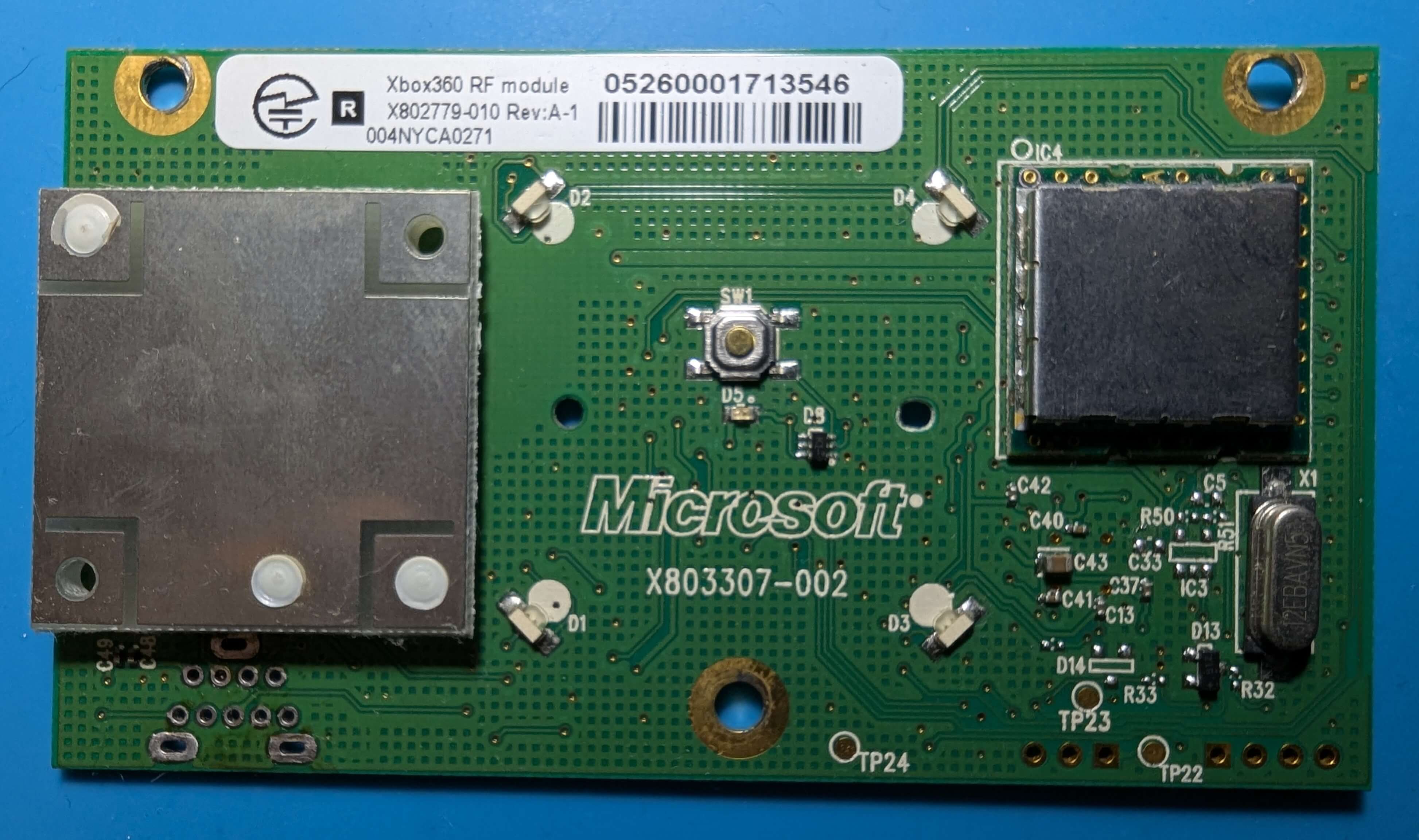
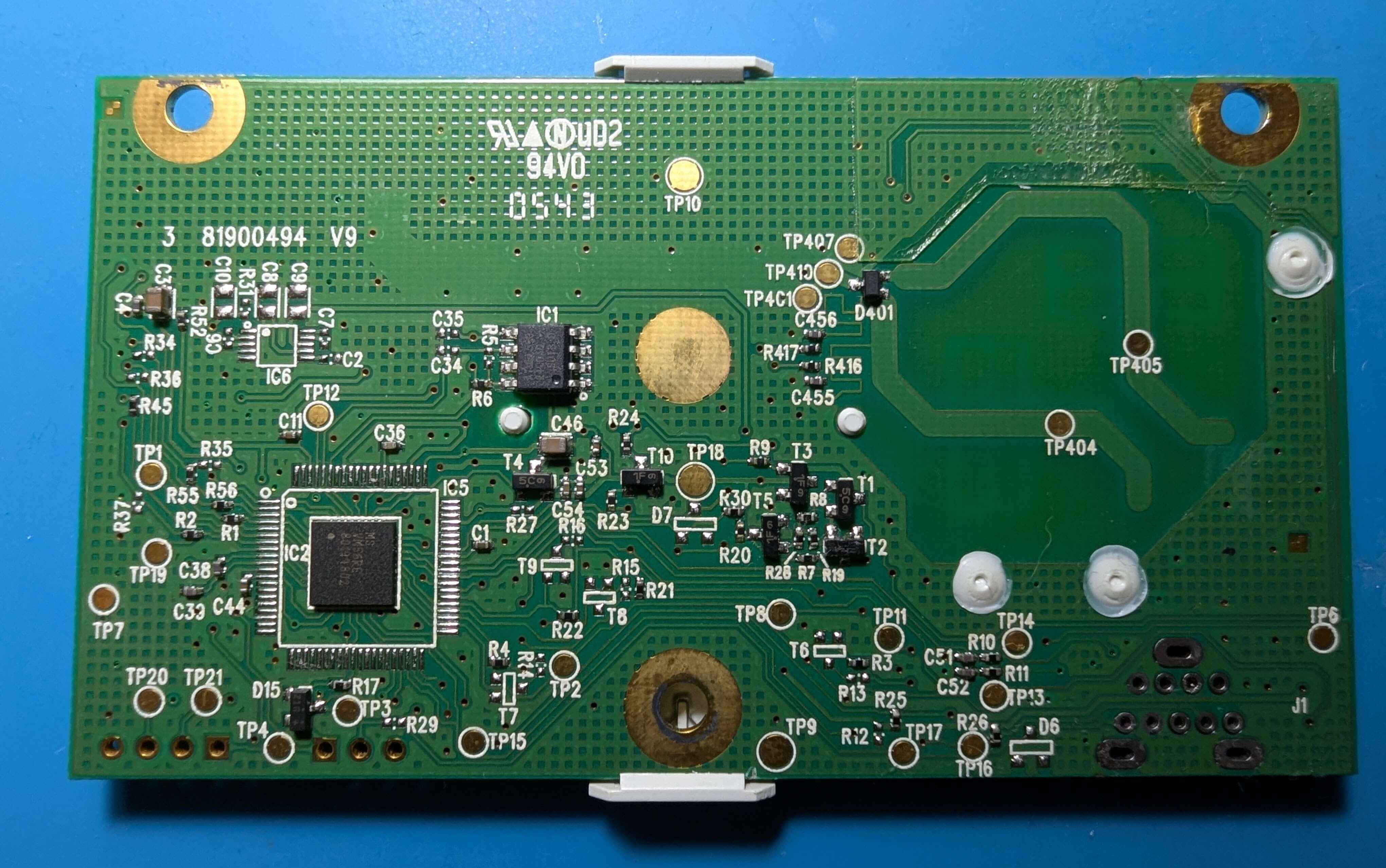
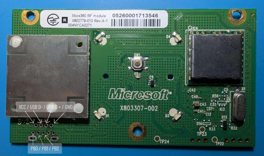
The main part of the project is the Xbox 360 Rf Module.
Other required parts:
- Voltage Regulator
- 3x M2x5mm Knurled Insert Nuts
- 1x Type C 3.1 Female Socket
- 3x M2 x 6 screws
- Attiny45
Uploading the code
I added this as the first step because you don’t want to forget about it.
In my project I used an Attiny45 with the bootloader from https://github.com/damellis/attiny.
You could do the same by installing the custom library and burning the bootloader while setting the clock to 16Mhz, Internal.
After that, upload the following code on your Attiny45.
/*
 * Xbox 360 RF Module Sync – ATtiny45 @16MHz
 * PB0 - SYNC button (RF pin 5)
 * PB1 - DATA line   (RF pin 6)
 * PB2 - CLOCK line  (RF pin 7)
 * VCC = 3.3V, GND = common
 * Uses internal pull-ups and frame repetition for Rev H
 */

#include <avr/io.h>
#include <util/delay.h>

// --- Pin map ---
#define SYNC_PIN   PB0
#define DATA_PIN   PB1
#define CLOCK_PIN  PB2

// --- Command sequences (10 bits) ---
const uint8_t LED_INIT[10]  = {0,0,1,0,0,0,0,1,0,0};
const uint8_t LED_ANIM[10]  = {0,0,1,0,0,0,0,1,0,1};
const uint8_t SYNC_CMD[10]  = {0,0,0,0,0,0,0,1,0,0};

// --- Send 10-bit command sequence ---
void sendData(const uint8_t *cmd) {
    DDRB |= (1 << DATA_PIN);
    PORTB &= ~(1 << DATA_PIN); // start LOW
    _delay_us(5);

    int prev = 1;
    for (uint8_t i = 0; i < 10; i++) {
        while (prev == ((PINB >> CLOCK_PIN) & 1)); // wait clock change
        prev = ((PINB >> CLOCK_PIN) & 1);

        _delay_us(5); // hold DATA before clock

        if (cmd[i]) PORTB |= (1 << DATA_PIN);
        else        PORTB &= ~(1 << DATA_PIN);

        _delay_us(10); // hold bit long enough for Rev H
        while (prev == ((PINB >> CLOCK_PIN) & 1)); // wait next edge
        prev = ((PINB >> CLOCK_PIN) & 1);
    }

    PORTB |= (1 << DATA_PIN); // idle HIGH
    DDRB &= ~(1 << DATA_PIN);
}

// --- Initialize RF LEDs ---
void initLEDs() {
    sendData(LED_INIT);
    _delay_ms(50);
    sendData(LED_ANIM);
    _delay_ms(50);
}

// --- Play moving ring animation during sync ---
void playSyncAnimation() {
    for (uint8_t i = 0; i < 3; i++) { // repeat ring 3 times for visibility
        sendData(LED_ANIM);
        _delay_ms(50);
    }
}

int main(void) {
    // pin setup
    DDRB &= ~((1 << SYNC_PIN) | (1 << CLOCK_PIN)); // inputs
    PORTB |= (1 << SYNC_PIN) | (1 << CLOCK_PIN) | (1 << DATA_PIN); // internal pull-ups

    _delay_ms(2000); // RF power-up delay
    initLEDs();

    uint8_t pressed = 0;
    uint16_t hold_time = 0;

    while (1) {
        if (!(PINB & (1 << SYNC_PIN))) { // active-low button
            if (!pressed) {
                pressed = 1;
                hold_time = 0;
            }
            _delay_ms(100);
            hold_time += 100;

            if (hold_time >= 1000) {
                sendData(SYNC_CMD);       // send sync command
                playSyncAnimation();      // moving ring during sync
                hold_time = 0;            // trigger once per press
            }
        } else {
            pressed = 0;
            hold_time = 0;
        }
    }
}
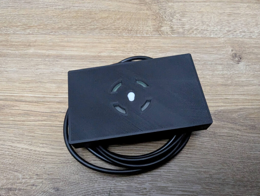
3D Printed Case
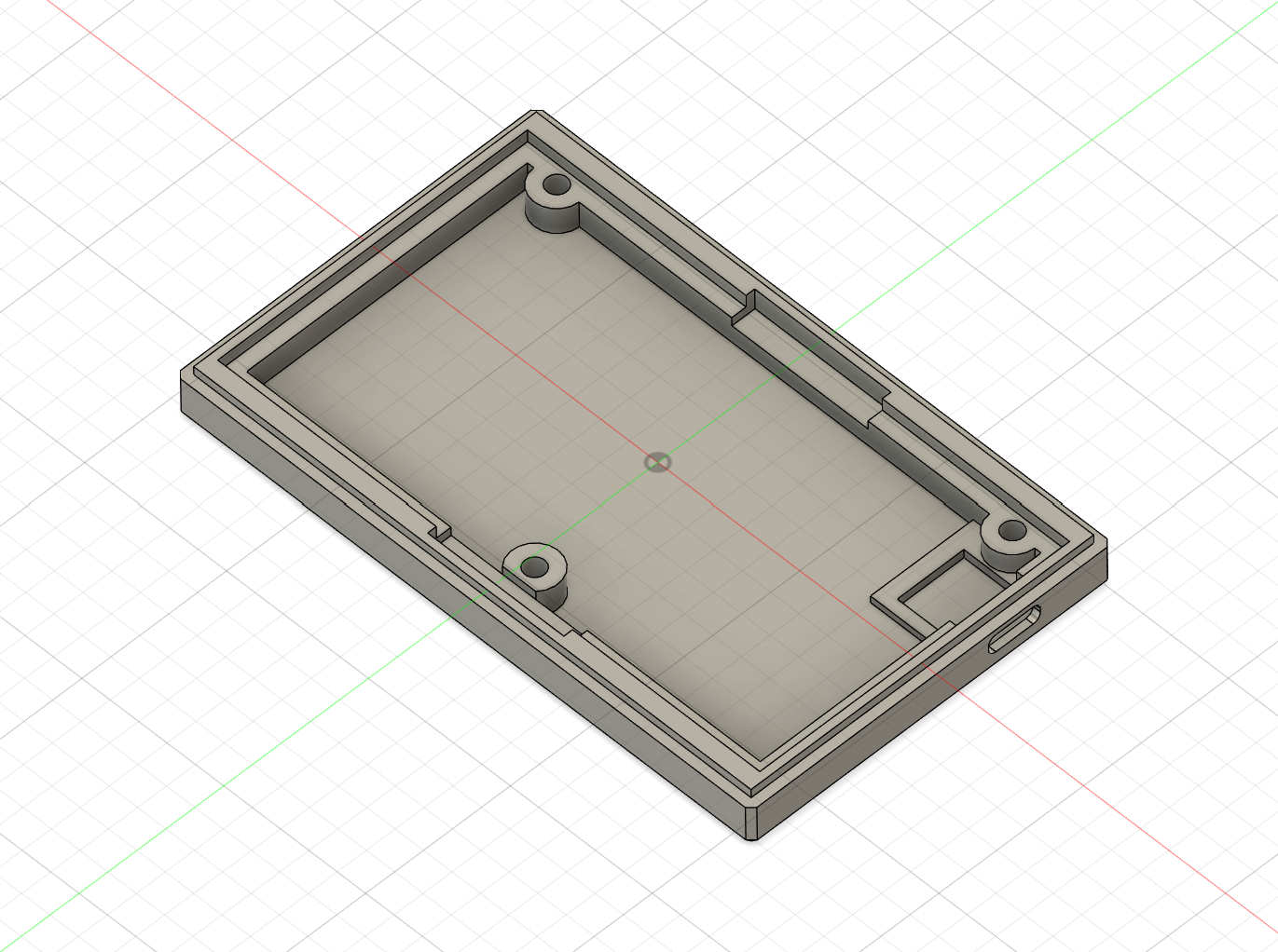
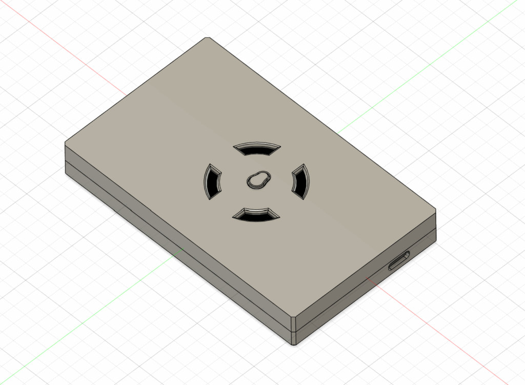
For this project I designed a simple 3D model in Fusion 360.
Download the files, and 3D print them, you’ll need this in the next steps.
https://makerworld.com/en/models/1911648-xbox-360-rf-module-box-diy-receiver
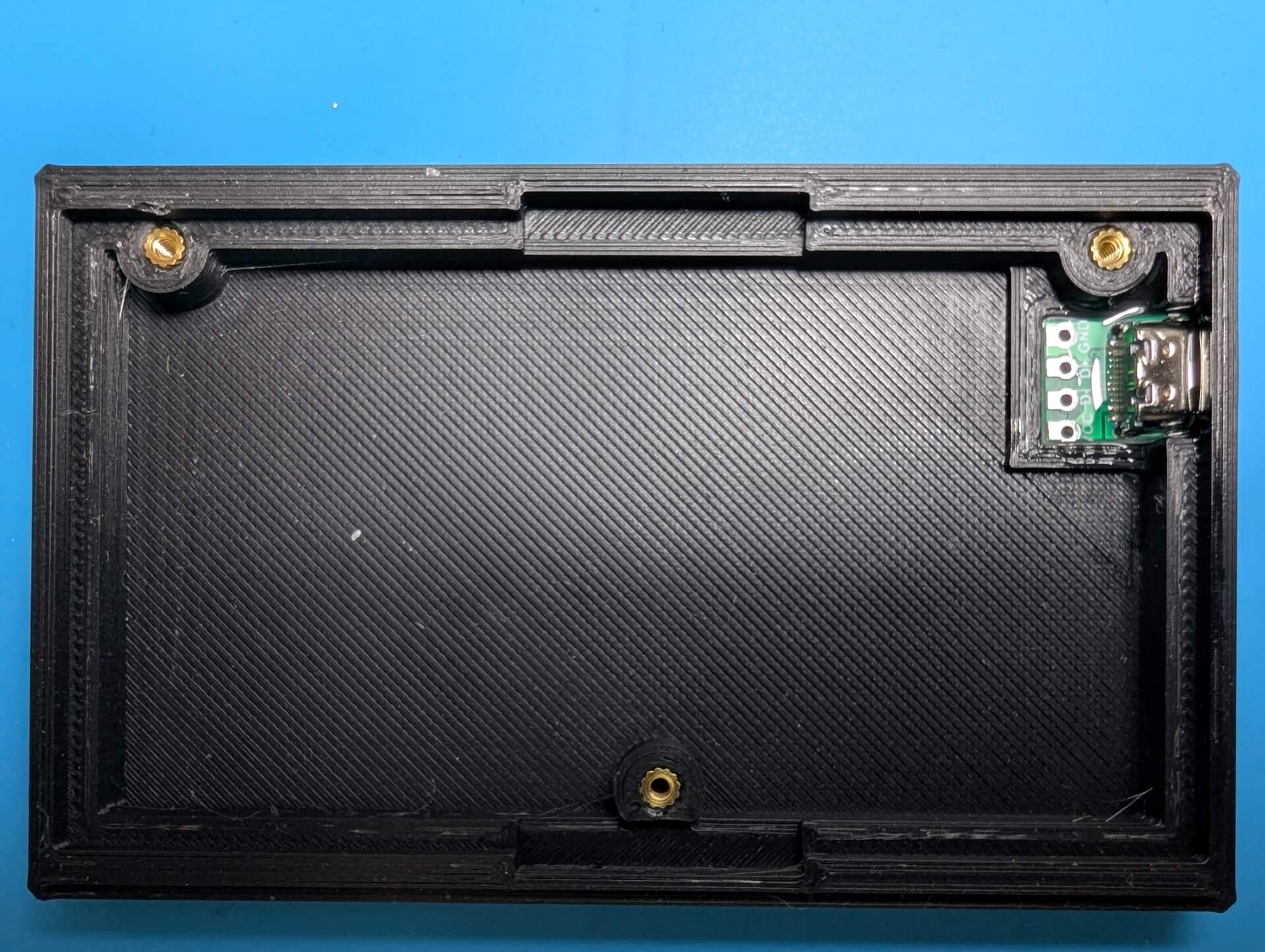
Preparing the 3D Printed case
For the next step, you’ll need:
- 3x M2x5mm Knurled Insert Nuts
- 1x Type C 3.1 Female Socket
Insert the knurled nuts and using a small amount of glue, place the USB C board.
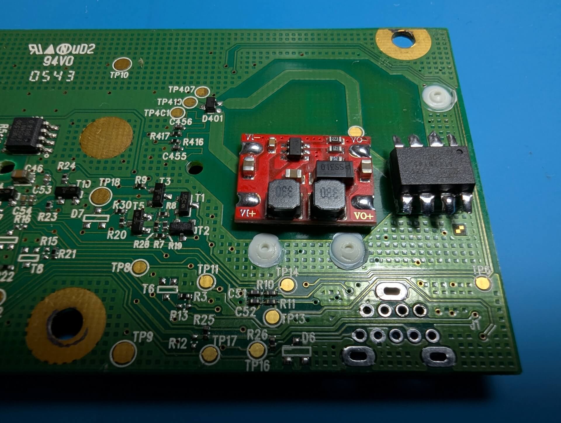
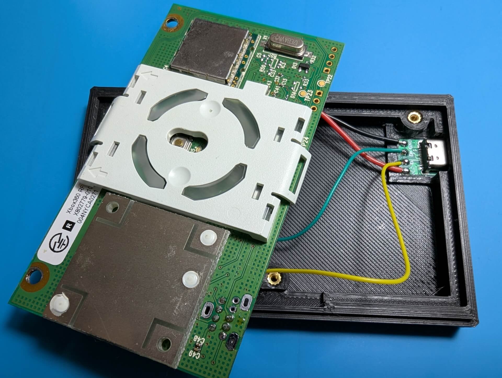
Preparing the RF Board
In the next step you’ll need to place the voltage regulator and the Attiny45 as well as making the right connections.
I used double tape to place the voltage regulator and attin45.
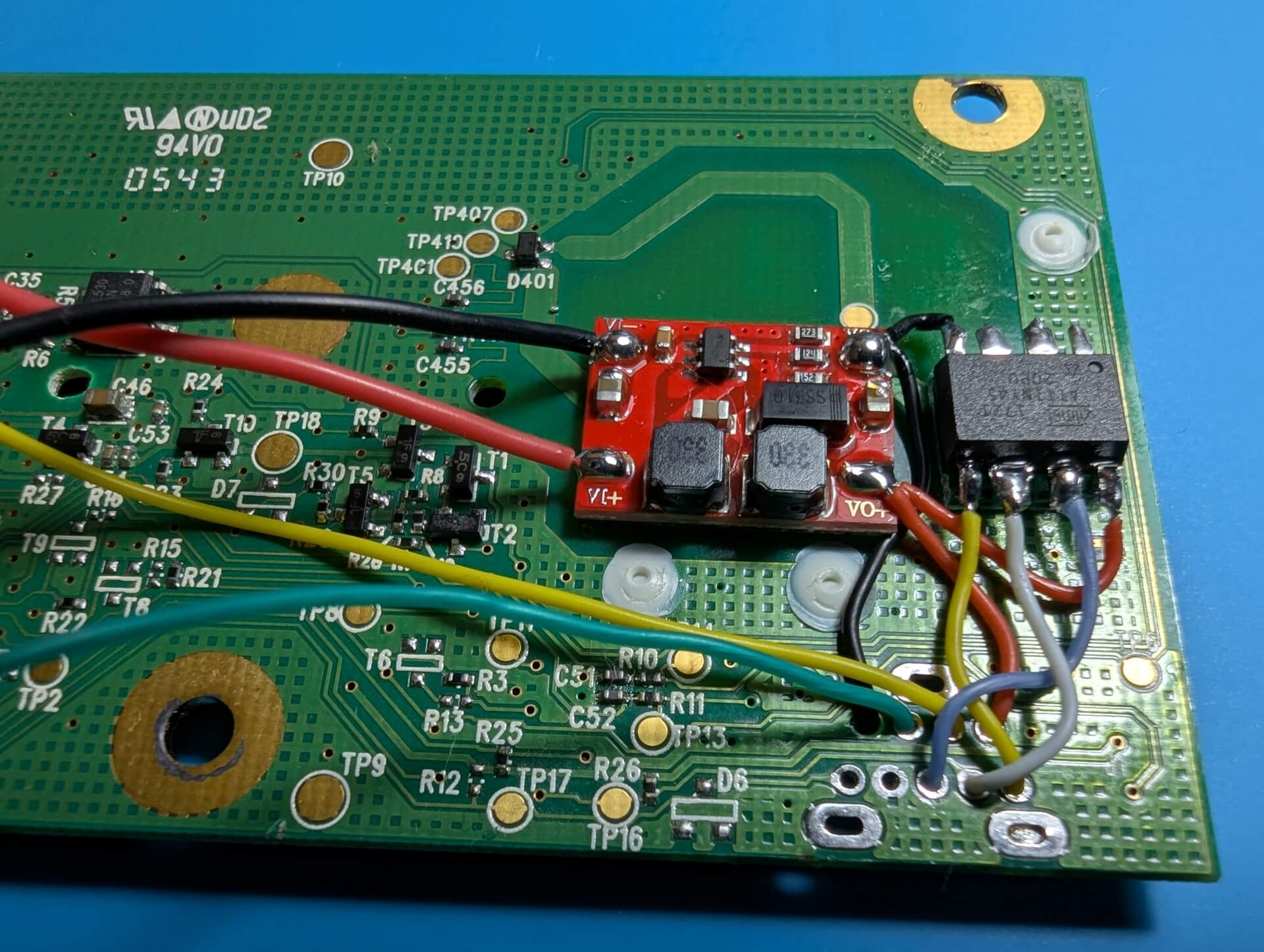
For the connections, you’ll need to use the following pinout:
ATTINY45 -> RF
- PB0 – SYNC button (RF pin 5)
- PB1 – DATA line (RF pin 6)
- PB2 – CLOCK line (RF pin 7)
USB -> RF + Voltage Regulator
- VCC -> Voltage Regulator VI+
- D- -> RF USB D-
- D+ -> RF USB D+
- GND -> Voltage Regulator V+
Voltage Regulator -> Attiny45 / RF
- VO+ -> RF VCC, Attiny45 VCC
- VO- -> RF GND, Attiny45 GND
Complete the connections and assemble the case
- As a final step, connect the following:
- VCC From Voltage Regulator -> VCC USB PCB
- GND From Voltage Regulator -> GND USB PCB
- RF USB D- -> D- USB PCB
- RF USB D+ -> D+ USB PCB
- Add the screws
- Test
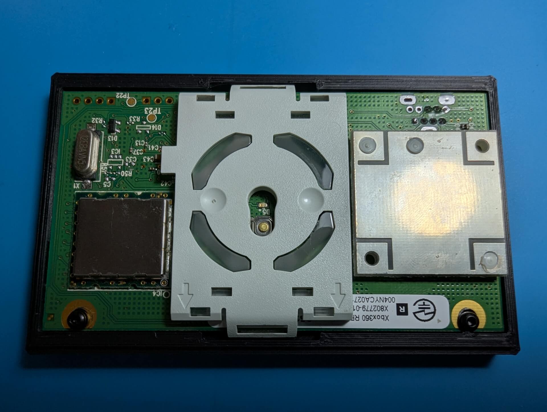
Note: You can add double tape on the pcb in order to hold the 3D printed part better.
Installing the drivers
If you plan on using this Xbox 360 receiver with RetroPie, just plug in the USB and have fun!
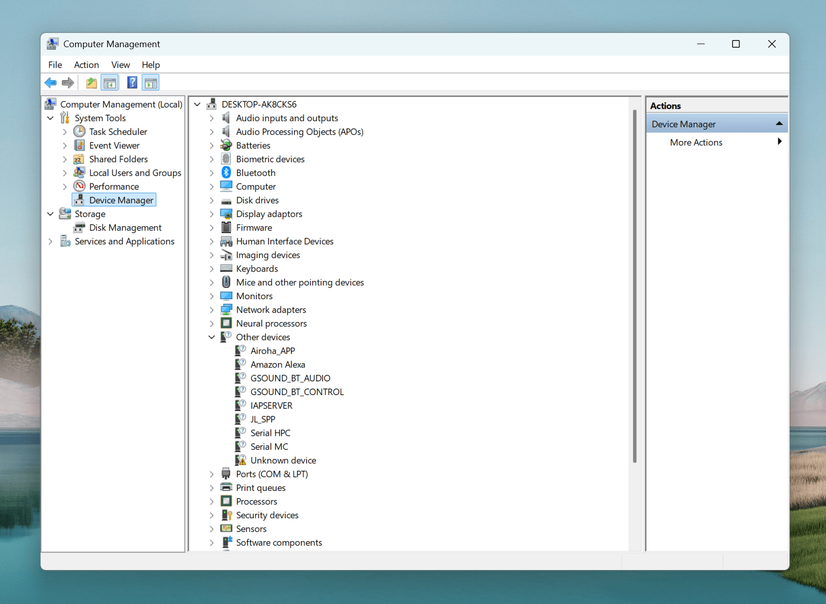
For Windows 11, the good part about this is the fact that the drivers are already on your computer, and you’ll only need to activate them.
In order to do this follow the next steps:
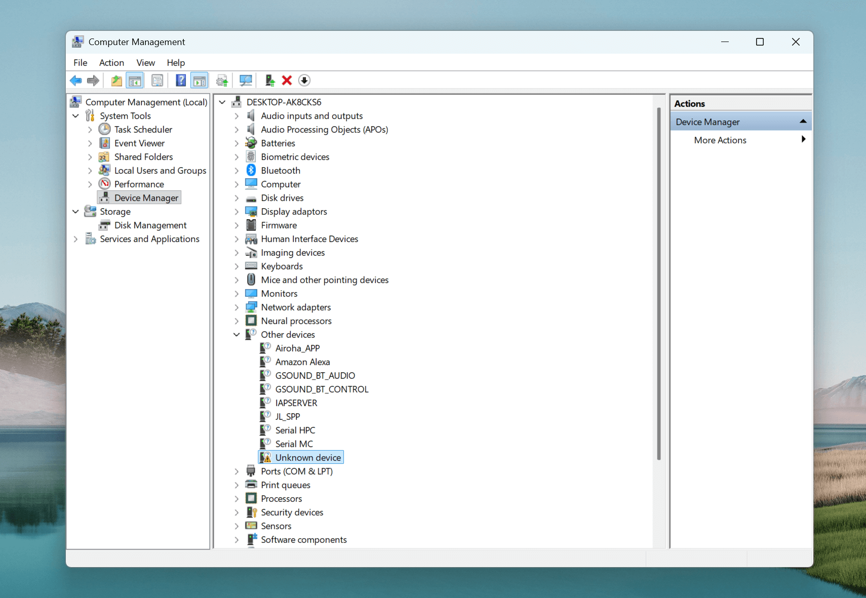
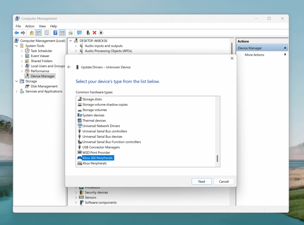
- Open your computer manager
- Click on device manager
- Right click on the unknown device and select “Update Driver”
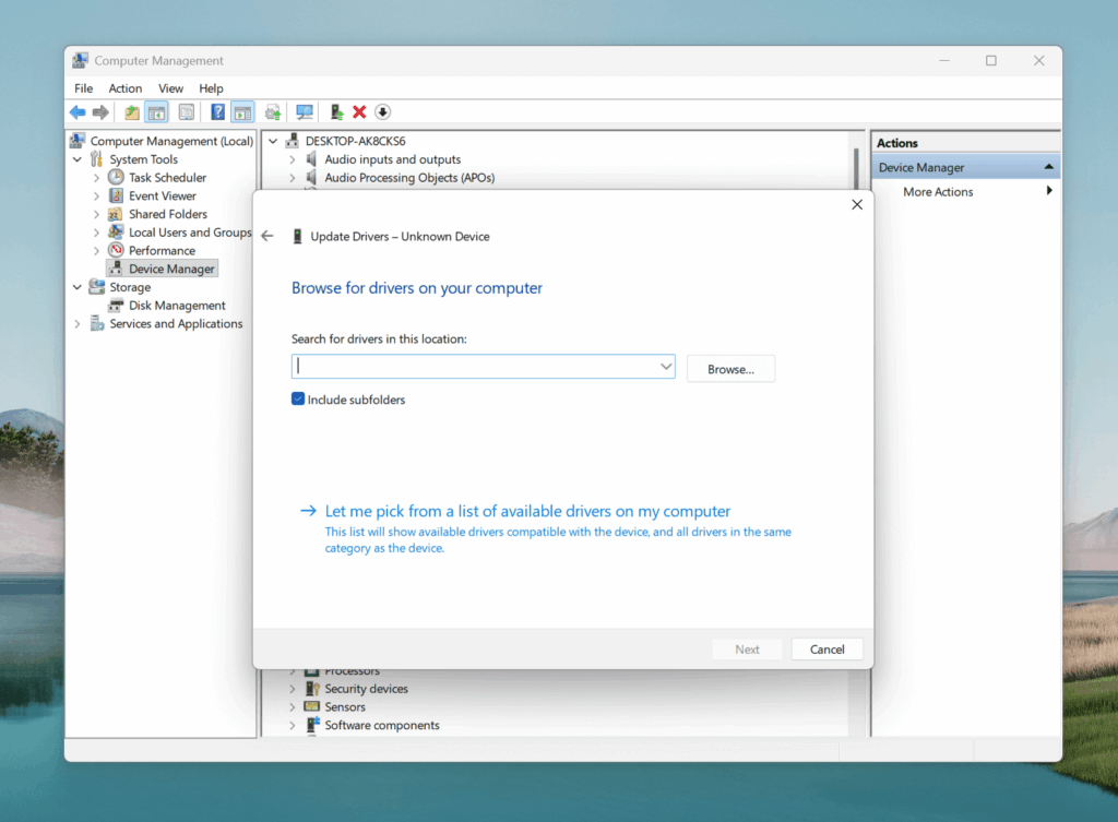
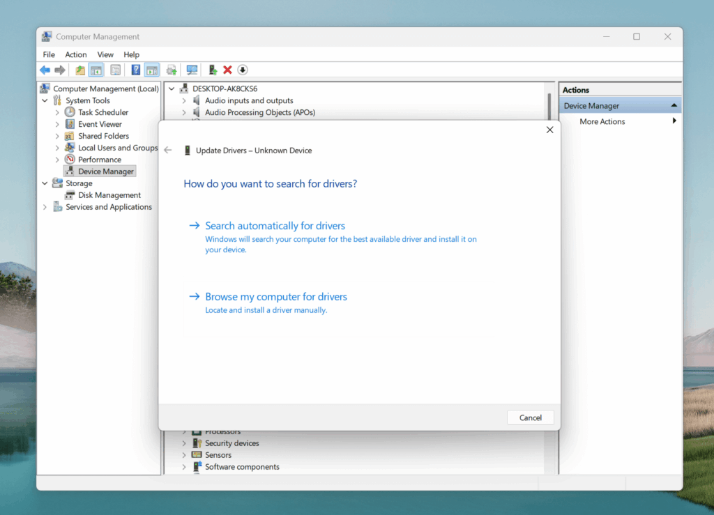
- Browse my computer for drivers
- Let me pick from a list of available drivers on my computer
- Scroll down and select “Xbox 360 Peripherals”
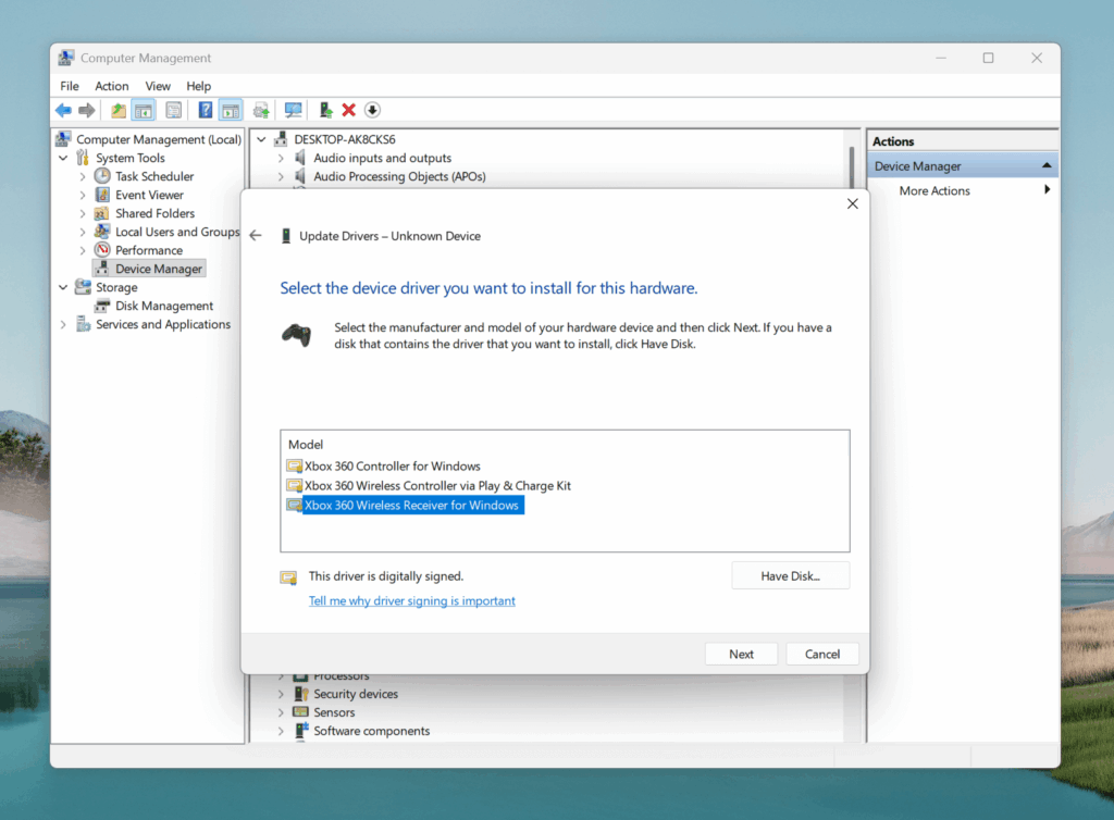
- Click next, and on the next screen select “Xbox 360 Wireless Receiver for Windows”
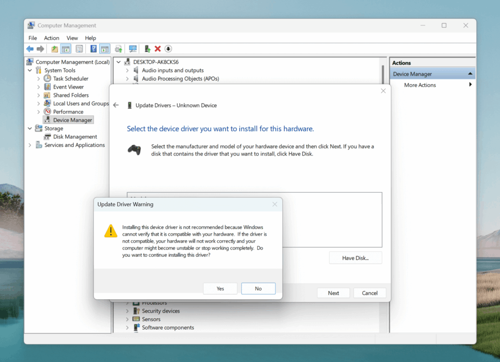
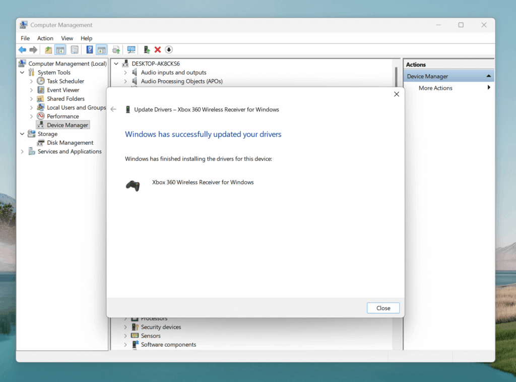
- Select “Yes” to install the drivers
- And, “Close”
Resources:
https://agarmash.com/posts/xbox-360-controller-receiver
https://www.electromaker.io/project/view/xbox-360-rf-module-controlled-with-an-arduino-1