I decided to keep this separate from the build in order to make all the steps easier to follow.
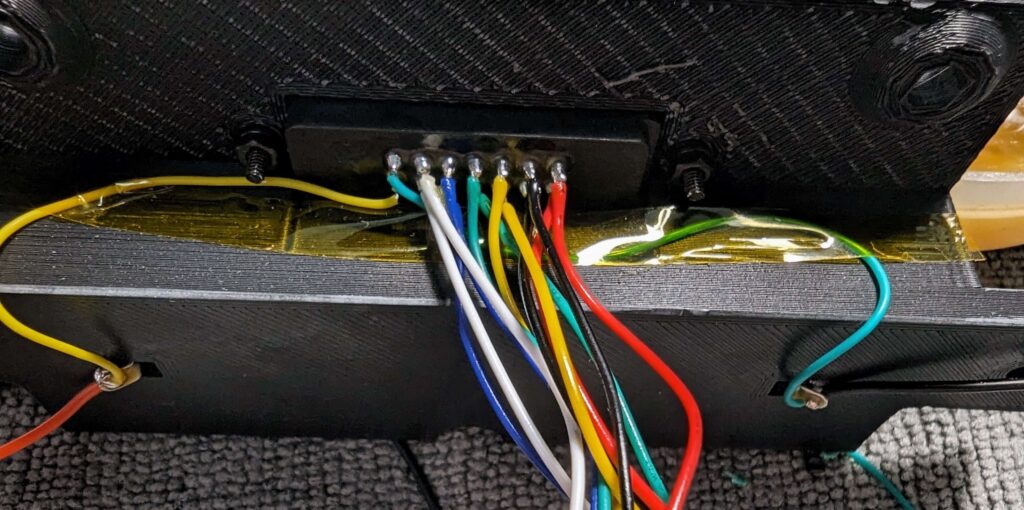
Note: Because the first pin is GND and my connector starts with a RED wire, it will be a bit confusing.
Also, I used pictures from a different build, where I tested a different shell, but that doesn’t really matter because, in the build tutorial, I’m using the final shell.
RX PCB
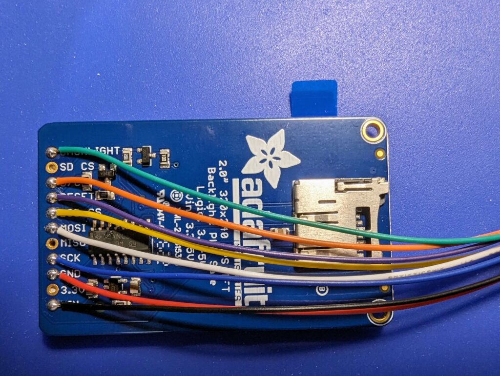
TFT Display
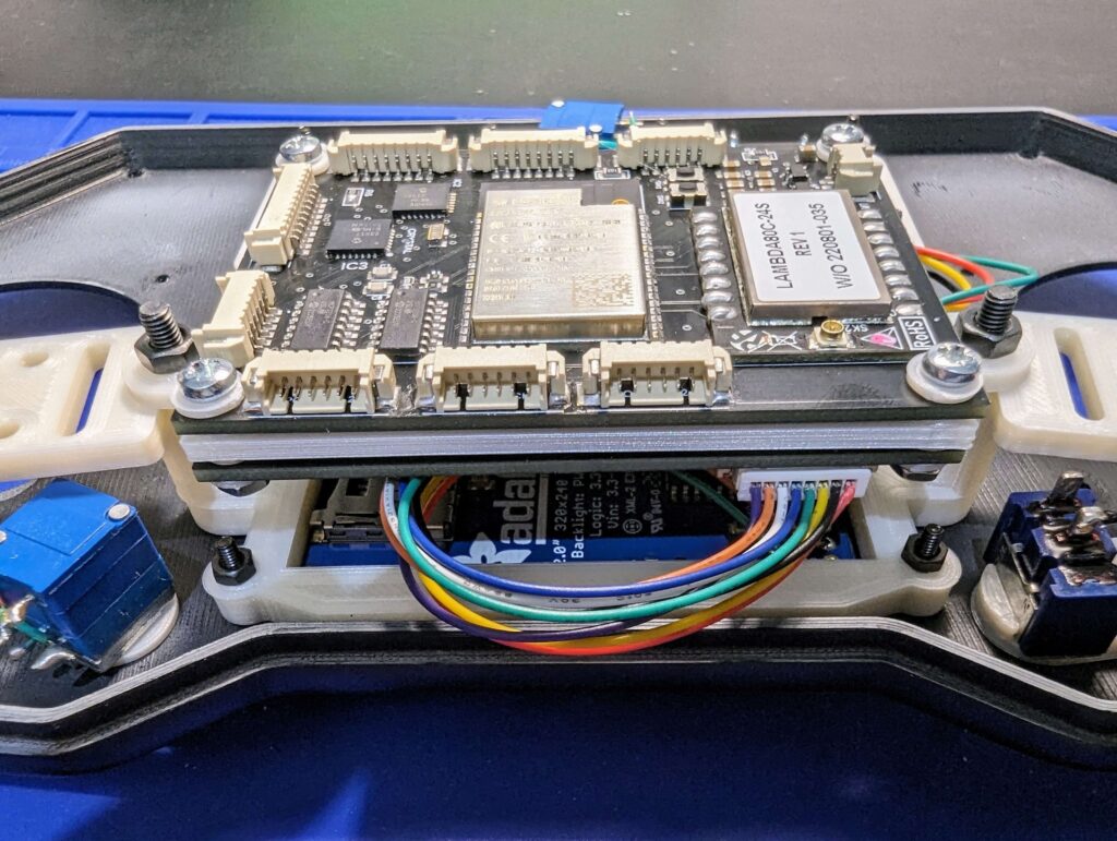
PCB
Backlight
GPIO27
D/C
GPIO4
Reset
GPIO15
LCD CS
GPIO25
MOSI
GPIO13
SCK
GPIO14
GND
GND
VIN
3.3v
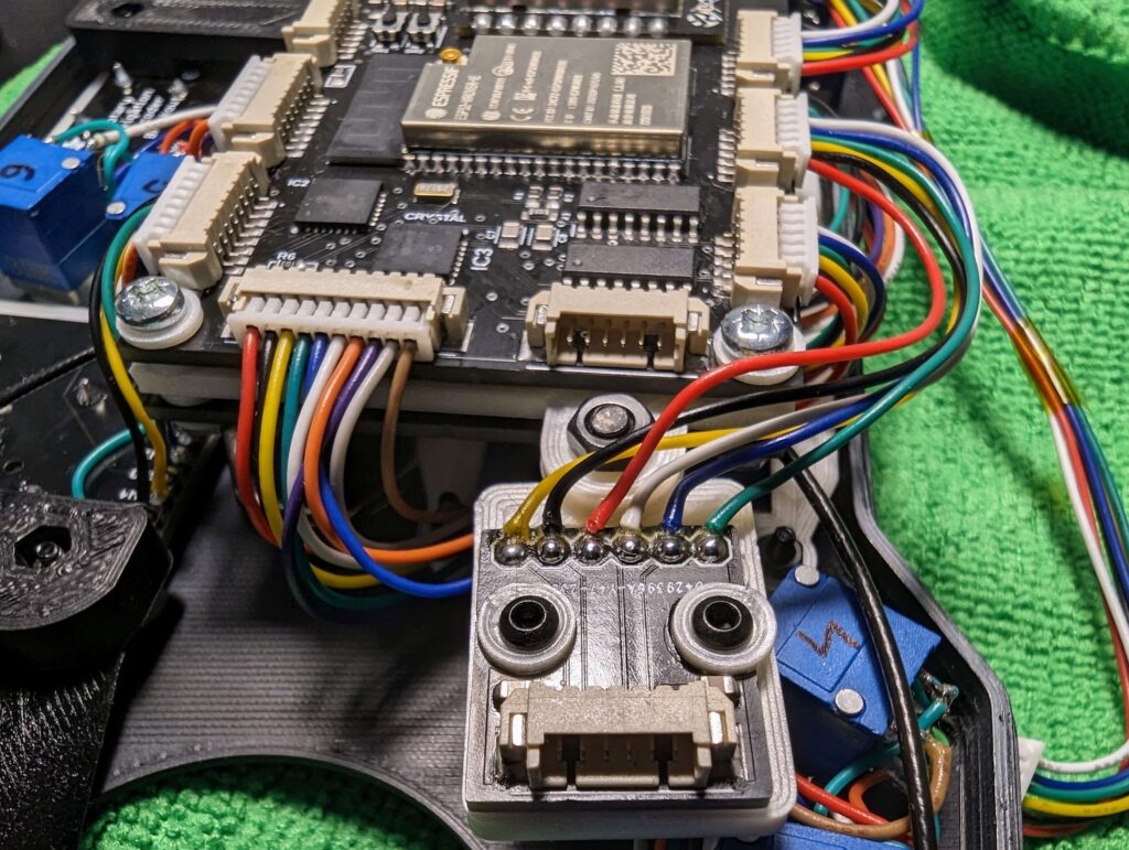
Push Buttons
PCB
Button 1 (green wire )
GPIO34
Button 2 (yellow wire)
GPIO39
Button 3 (black wire)
GPIO36
Common GND (red wire)
GND
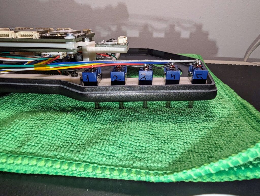
Switches
PCB
Switch #1 – Black Wire
SW1
Switch #2 – Yellow Wire
SW2
Switch #3 – Green Wire
SW3
Switch #4 – Blue wire
SW4
Switch #5 – White wire
SW5
Common GND (red wire)
GND
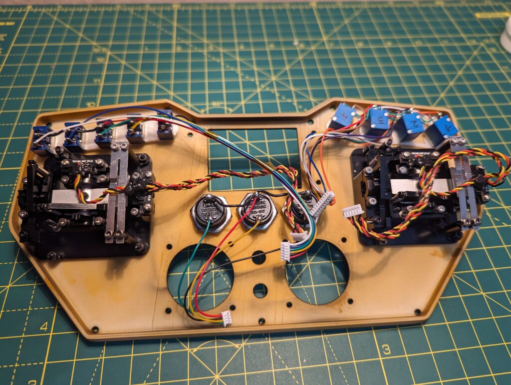
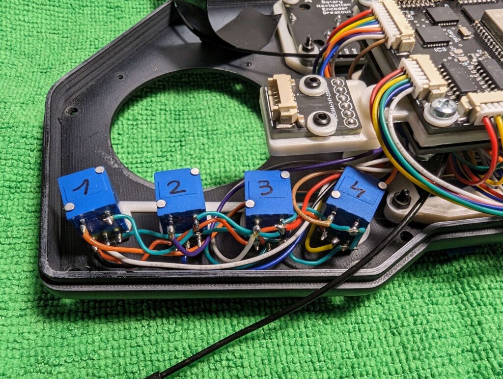
For the potentiometers, please check the datasheet and make sure to connect the right VCC to 3.3V and GND to GND. In case you’ll invert them, the reading will also be inverted.
Potentiometer
PCB
POT #1 signal
POT1
POT #2 signal
POT2
POT #3 signal
POT3
POT #4 signal
POT4
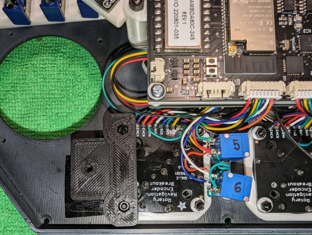
POT #5 signal
POT5
POT #6 signal
POT6
Pot Switch #1
POT1_SW
Pot Switch #2
POT2_SW
Pot Switch #3
POT3_SW
Pot Switch #4
POT4_SW
Pot Switch #5
POT5_SW
Pot Switch #6
POT6_SW
Common GND
GND
Common VCC
3.3V
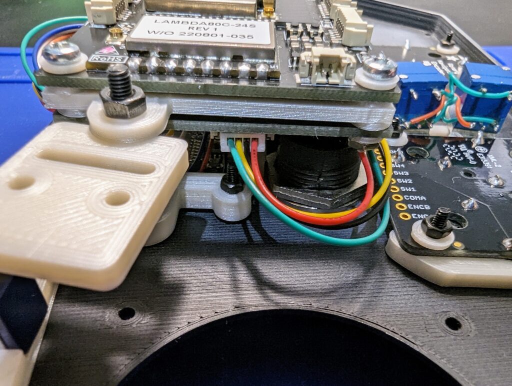
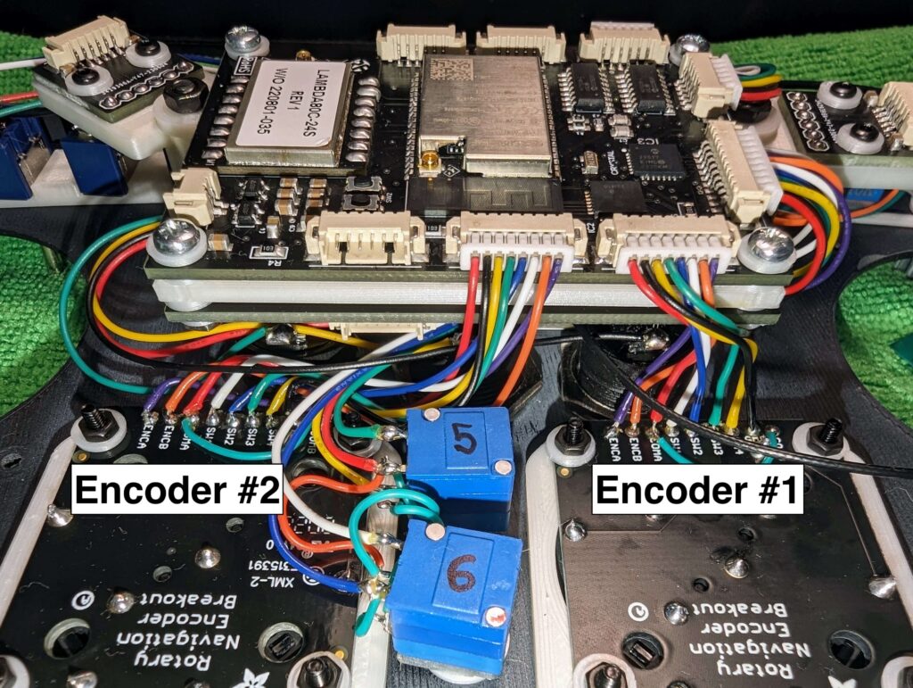
Encoder #2
PCB
COMB
GND
SW5
ANO2_SW5
SW4
ANO2_SW4
SW3
ANO2_SW3
SW2
ANO2_SW2
SW1
ANO2_SW1
COMA
GND
ENCB
ANO2_ENCB
ENCA
ANO2_ENCA
Encoder #1
PCB
COMB
GND
SW5
ANO1_SW5
SW4
ANO1_SW4
SW3
ANO1_SW3
SW2
ANO1_SW2
SW1
ANO1_SW1
COMA
GND
ENCB
ANO1_ENCB
ENCA
ANO1_ENCA
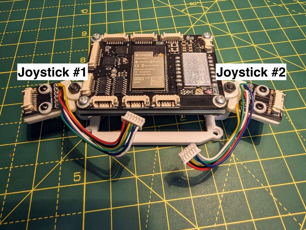
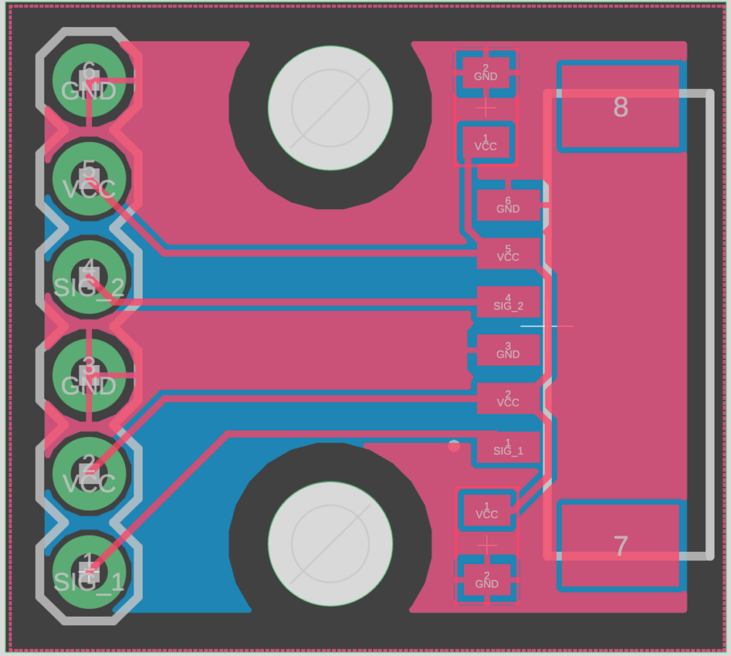
Joystick #1 PCB
PCB
GND (second GND)
GND
VCC (second VCC)
3.3V
SIG_1
JOYSTICK_X1
GND (first GND)
GND
VCC (first VCC)
3.3V
SIG_2
JOYSTICK_Y1
Joystick #2 PCB
PCB
GND (second GND)
GND
VCC (second VCC)
3.3V
SIG_1
JOYSTICK_X1
GND (first GND)
GND
VCC (first VCC)
3.3V
SIG_2
JOYSTICK_Y1
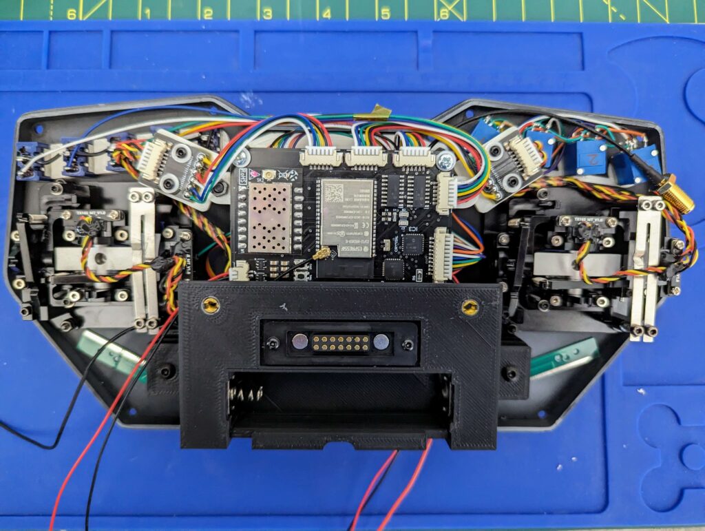
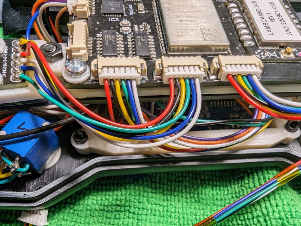
For the programming connector, the far left 2 pins are connected directly to the battery. It could be used to either charge the battery or, just power the remote from an external source.
The yellow one is VCC while the Blue(ish) one is GND.
I’ll only list the FTDI pinout for a single PCB, as I’m using the same pinout for the second one. You can see that I have 2x white, blue, green, yellow, black and red wires.