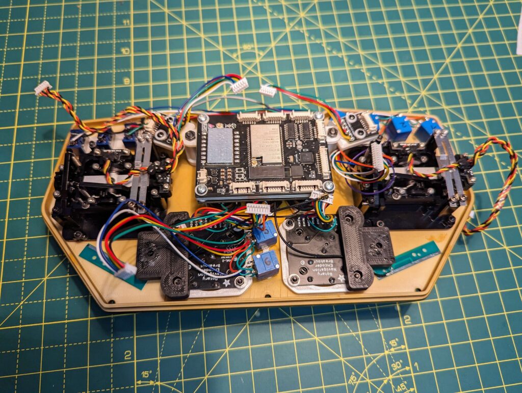
After the PCB assembly ( download Gerber files ) and 3D printing of the available STL files ( download STL files ) the final part is the remote assembly.
I’ll try to write the steps as detailed as possible, but if there are any questions just add a comment or join our discord server and I’ll be more than happy to reply.
If you want to read more about how I connected everything, please check this article https://microknot.dev/rc-transmitter-wiring-tutorial-esp32-sx1280/
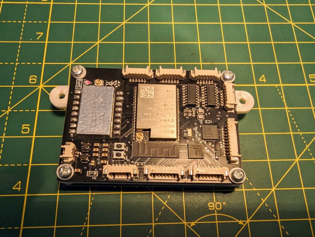
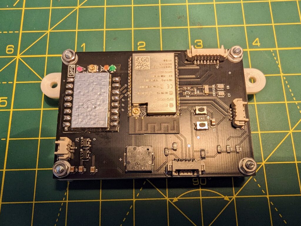
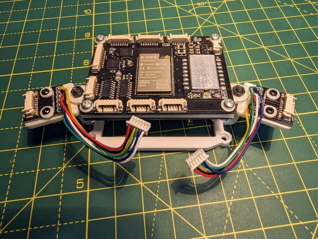
Step 1: PCB Assembly
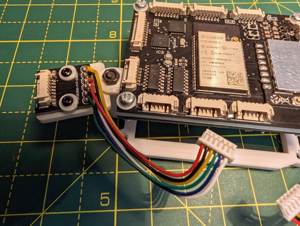
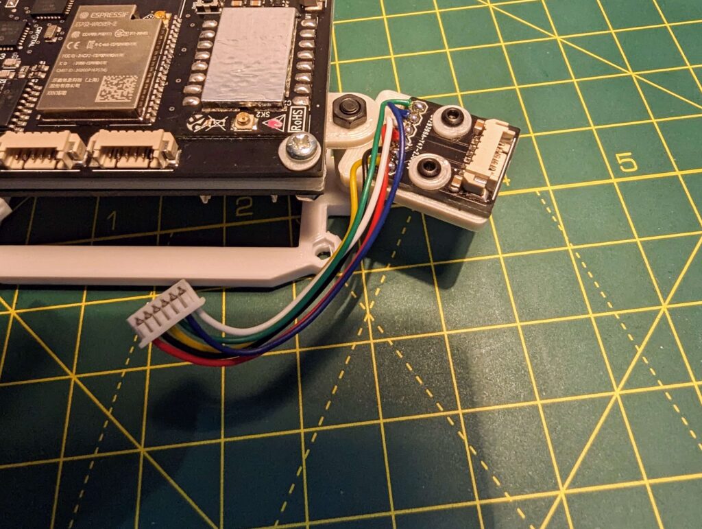
Because you’ll need to cut the wires at an approximate length, it will be good to have the PCB holder ready.
As you’ll see in the photos I added spacers in order to prevent scratching the PCBS. What you can’t see in the photos, is that I also added spacers under the PCB.
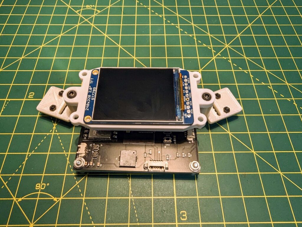
Note: You don’t need to connect the screen yet, you could do that later.
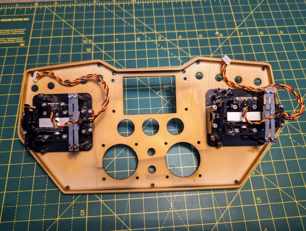
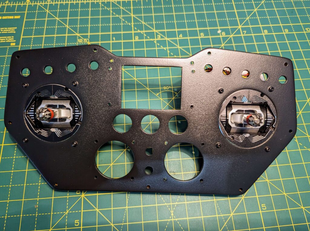
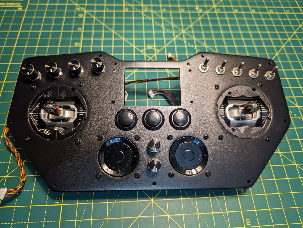
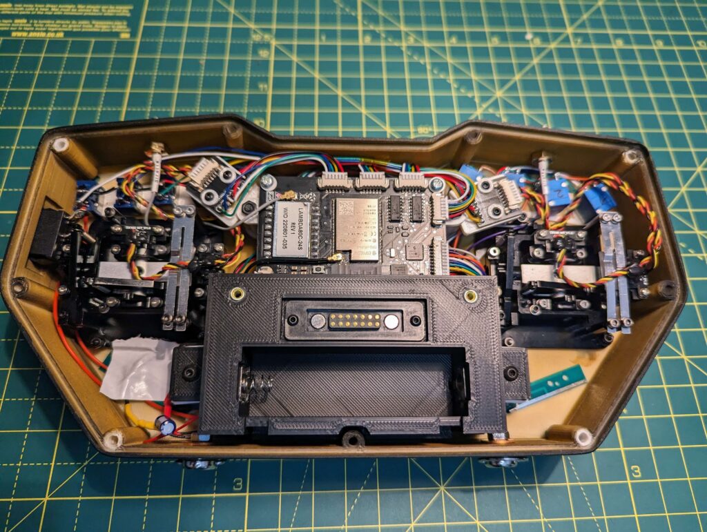
Step 2: Add the Joysticks
Step 3: Add the main potentiometers, switches and the push buttons
Note: Based on the pins’ length you may need to either cut or bend the connectors from the push buttons.
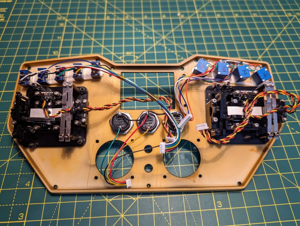
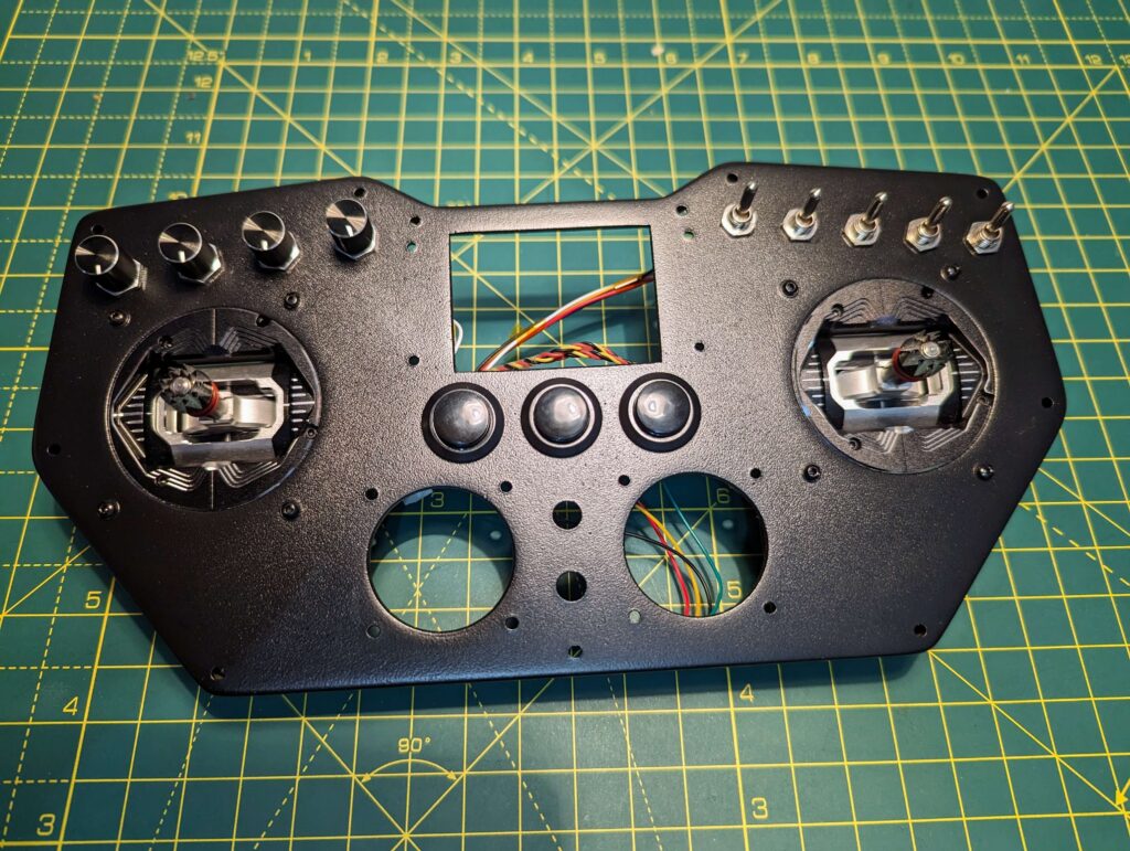
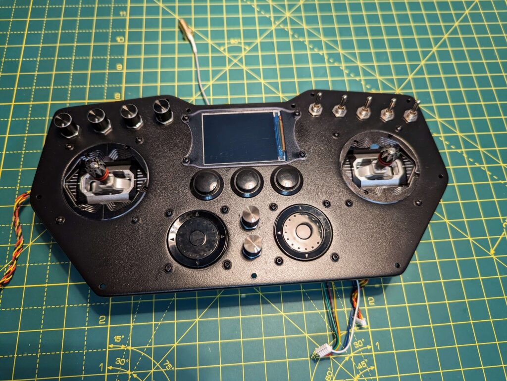
Step 4: Add the rotary encoders, the two potentiometers and the two 2.4Ghz antennas.
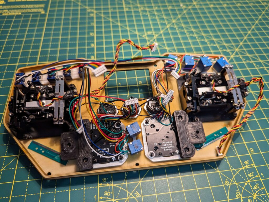
Step 5: Connect the UFL to SMA Bulkhead Socket for the RX, the 2.4ghz antenna, the screen and the push buttons, after that use the screws to keep everything in place.
For my remote, I used a CNC3018 in order to cut the screen protector.
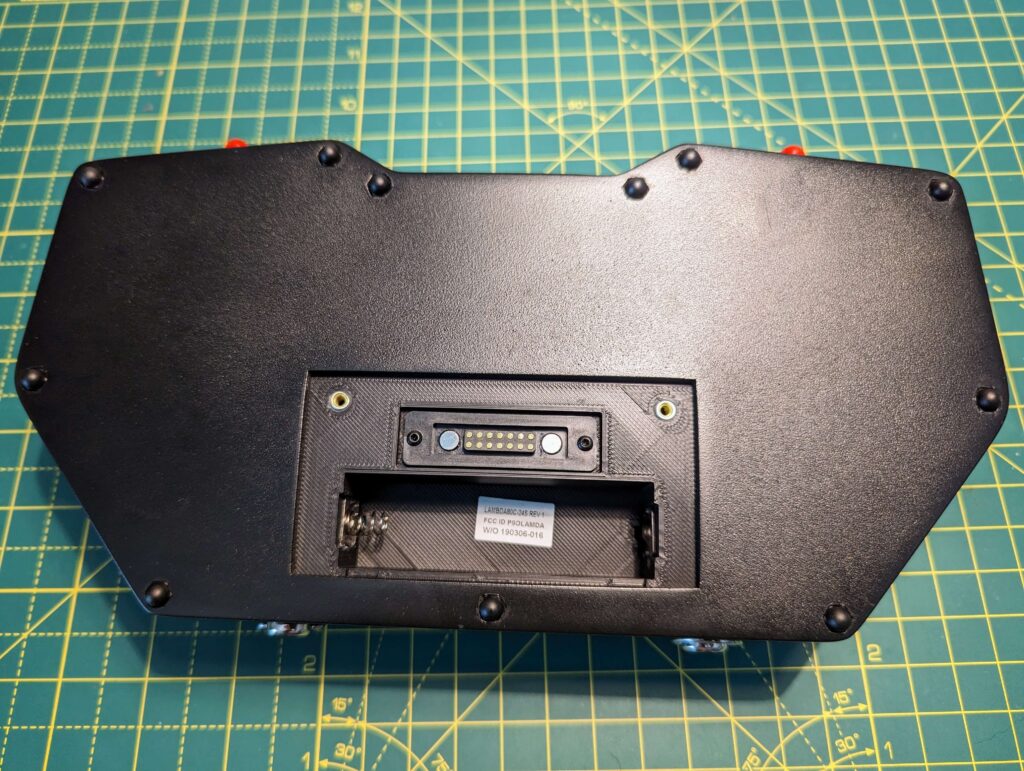
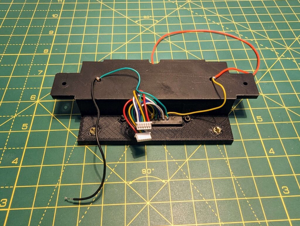
Step 6: Prepare the battery holder
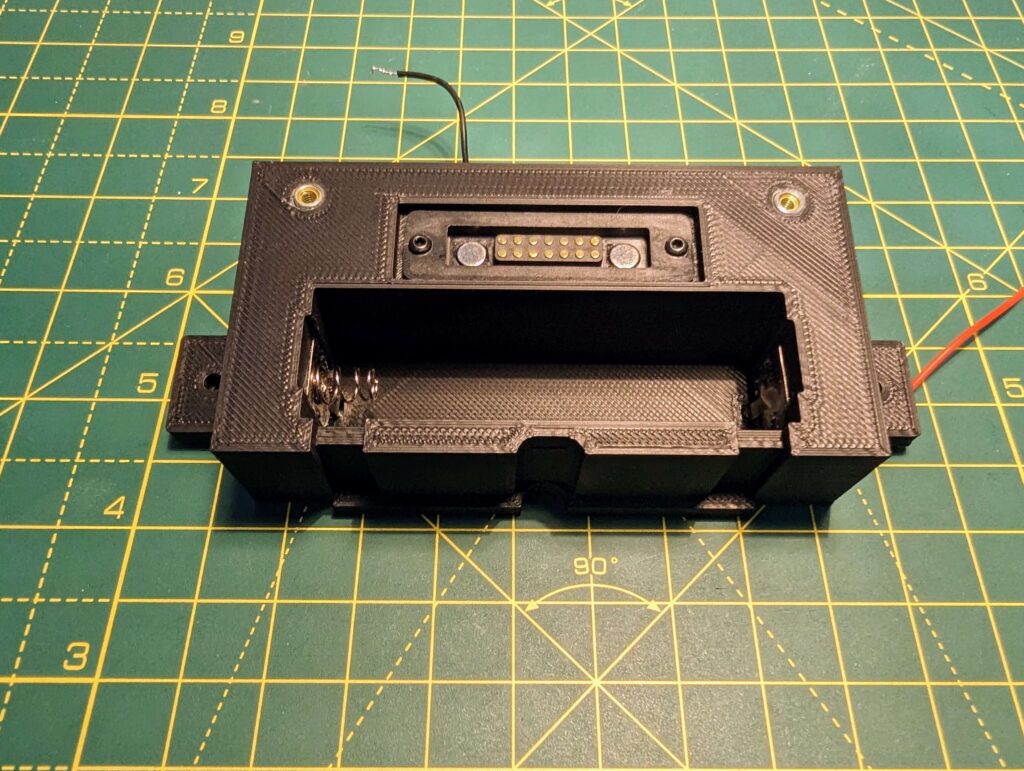
Step 7: Connect the UFL to SMA Bulkhead Socket and the 2.4Ghz antenna for the TX; after that add the battery holder.
Before closing up the remote, please remember to add the neck strap connectors and to make sure that the UFL to SMA connectors and potentiometers are secure.
If possible, try and move the potentiometers a few times at maximum/minimum, as well as add and remove the antennas to see if everything is secure.
The final step is adding the cover.